Loop wiring diagram wire current connection 20ma ma 20 divize sensor converter power voltage tide examples arduino signal tester supply [diagram] easy wire loop diagrams ⭐ 3 wire 4 20ma wiring diagram schematic ⭐ 2 wire 4 20ma wiring diagram
4 to 20 mA Current Loops Made Easy | Harold G Schaevitz Industries LLC
4 to 20 ma transmitter circuit operation How to do the 4-20ma wiring? 2-wire 4-20 ma sensor transmitters: background and compliance voltage
20ma signal converter rs232 voltage 5vdc resistance vdc volt supply resistor ohm volts sensorsone required allow
4 20ma wiring diagram4 to 20 ma current loops made easy Ma 20 current loop wire powered loops temperature system figure easy made sensors use typical2 wire 4-20ma wiring diagram.
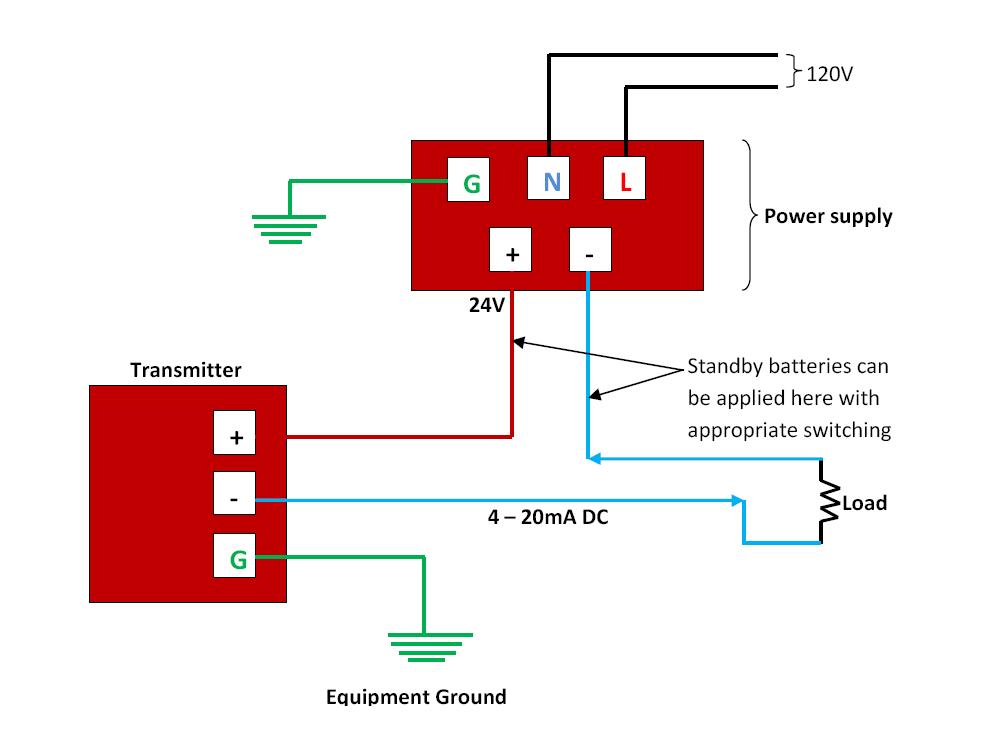
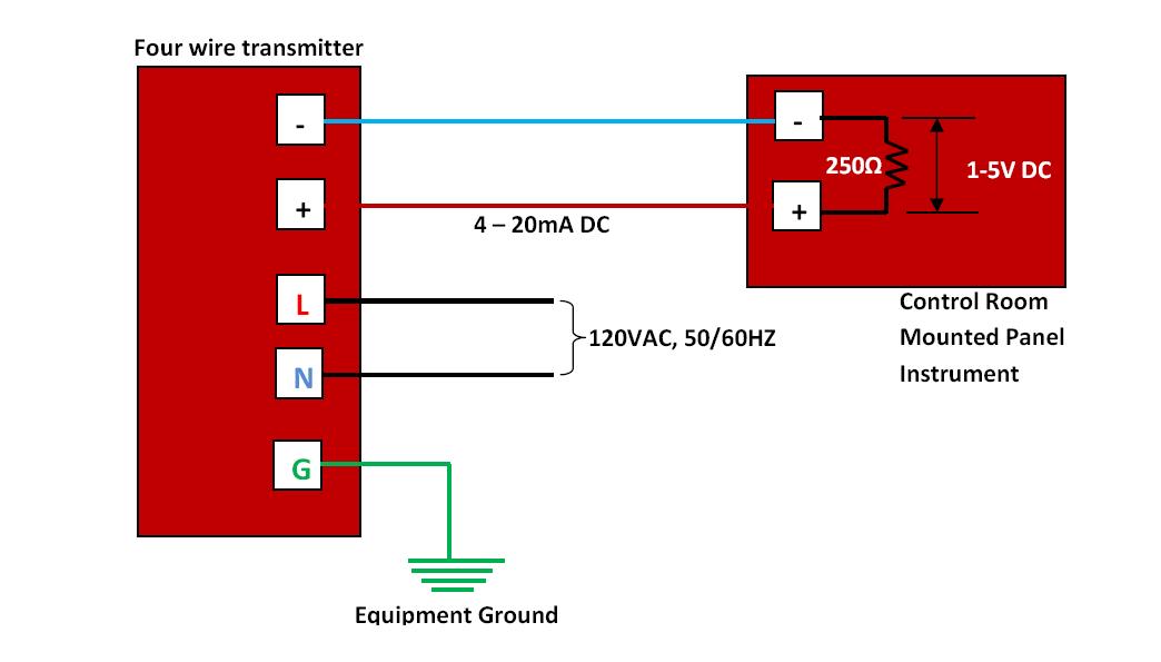
4-20 ma transmitter wiring: 4wire transmitter connection & 2wire loop4 20ma wiring diagram Foundation fieldbus wiring diagram4 to 20 ma current loop output signal.

2 wire 4 20ma wiring diagram
4 to 20 ma current loops made easy2 wire 4 20ma wiring diagram Good product online free shipping & free returns meter milliamp current20ma transmitter instrumentation wiring converter fieldbus analog output sensor schematic input plc signal foundation transducer principle communication sensing instrumentationtools variables.
How to wire a 4-20ma transmitter?|4wire & 2wire (loop poweredGreen hub Current loop connectionCircuit transmitter instrumentation.

Difference between 2 wire and 4 wire
Basics of the 4Ma current 20 loop wire powered loops temperature system figure easy made sensors use typical 4 20ma wiring diagramTwo wire 4 20ma circuit.
.